SiC and GaN: How Wide-Bandgap Semiconductors Are Reshaping EVs and Renewable Energy

Why Silicon Hits a Wall
For fifty years, Moore’s Law let silicon semiconductors shrink, speed up, and get cheaper. But in power electronics, silicon was never truly comfortable. Power devices must handle high voltage, switch at high frequencies, and operate in environments well above 100°C — and silicon hits a fundamental wall on all three fronts simultaneously.
On voltage, silicon’s critical electric field is roughly 0.3 MV/cm. Push past it and the on-resistance skyrockets as you increase doping concentration. On frequency, electron mobility degrades sharply under high electric fields, capping switching speeds. On temperature, silicon devices top out around 150–175°C before thermal runaway sets in.
These are not engineering challenges — they are limits written into silicon’s band structure. To go further, you need a different material.
The Wide-Bandgap Answer
The bandgap is the energy gap between a material’s valence band and conduction band — the fundamental parameter that determines electrical breakdown strength, carrier mobility, and thermal tolerance. Silicon sits at 1.12 eV. Silicon carbide (SiC) measures roughly 3.26 eV. Gallium nitride (GaN) comes in at about 3.4 eV.
That 3× increase in bandgap triggers a cascade of benefits. Critical electric field jumps by roughly 10×. On-resistance drops dramatically for the same voltage rating. And the maximum operating temperature pushes past 300°C for SiC, more than double what silicon can survive.
The result: a SiC or GaN device built for the same voltage can be smaller, switch faster, and waste less heat than its silicon counterpart. But the two materials excel in different regimes.
SiC: The Workhorse of Electric Vehicles
SiC’s strength is high voltage and high efficiency. Its thermal conductivity — 4.9 W/cm·K, roughly three times that of silicon — means heat dissipates quickly, making it ideal for high-power applications. Tesla’s Model 3 was the first vehicle to deploy SiC MOSFETs at scale in its traction inverter, pushing inverter efficiency past 97% while shrinking module size.
SiC substrates naturally support high blocking voltages. 1,200V and 1,700V devices are now standard in EV traction inverters, onboard chargers, and DC-DC converters. Solar inverters and grid-tied energy storage systems are following the same trajectory.
Manufacturing SiC, however, is far harder than silicon. The crystal growth process itself is the bottleneck.
Crystal Growth: PVT Step by Step
The dominant method for producing SiC single crystals is physical vapor transport (PVT), sometimes called the modified Lely method. A graphite crucible is loaded with high-purity SiC source powder at the bottom and a seed crystal mounted at the top. The crucible is sealed in an argon atmosphere and heated inductively to 2,200–2,500°C — far hotter than silicon’s 1,415°C melt point, and above SiC’s own decomposition threshold.
At these temperatures, the source powder sublimates directly into vapor-phase Si, Si₂C, and SiC₂ species. A carefully maintained temperature gradient — roughly 10–30°C/cm, with the seed cooler than the source — drives the vapor upward. At the seed, the vapor species recombine and condense, depositing SiC layer by layer. A single boule takes days to weeks to grow, and the process is exquisitely sensitive: a gradient deviation of a few degrees across the growing crystal face triggers polytype switching from 4H-SiC to 6H-SiC or 3C-SiC, rendering the boule electrically worthless.
High-temperature chemical vapor deposition (HTCVD) offers an alternative. Instead of sublimating solid source powder, HTCVD injects silane (SiH₄) and a hydrocarbon gas (typically ethylene or propane) into a heated chamber around 2,000°C. The gases react in the vapor phase and deposit SiC on the seed crystal. HTCVD provides tighter control over stoichiometry and impurity incorporation, enabling higher-purity crystals and sustained growth rates. The trade-off is equipment complexity: managing reactive gases at 2,000°C requires materials and gas-flow engineering that tilt the economics in favor of PVT for volume production. Most commercial SiC boules today are PVT-grown; HTCVD remains a niche for ultra-high-purity or semi-insulating substrates used in GaN-on-SiC RF devices.
Defects That Kill Yield
SiC wafers carry a hierarchy of crystallographic defects, each with distinct consequences for device performance.
Micropipes are hollow cylindrical voids — screw dislocations with giant Burgers vectors — that run axially through the crystal. A single micropipe penetrating an active device area creates a short-circuit path, killing the die outright. Micropipe density has dropped from hundreds per cm² in the 1990s to below 1 per cm² on premium substrates, but zero-micropipe wafers are not yet the industry standard.
Threading screw dislocations (TSDs) and threading edge dislocations (TEDs) — collectively at densities of 10³–10⁴ cm⁻² — contribute to leakage current, reduced carrier lifetime in the drift layer, and gate oxide reliability degradation. TSDs are the more damaging variety: their spiral growth step creates pits in epitaxial layers that concentrate electric fields during reverse bias.
Basal plane dislocations (BPDs) lie in the (0001) basal plane and are notorious for dissociating into Shockley partial dislocations during forward-biased operation. The dissociation generates single-layer stacking faults that expand across the drift region, increasing forward voltage drop (Vf drift) until the device no longer meets its datasheet specification. BPD-to-stacking-fault conversion is the dominant long-term degradation mechanism in SiC bipolar devices and body diodes.
Stacking faults and carrot defects in epitaxial layers further degrade minority carrier lifetime and increase on-resistance. Defect classification has moved from academic taxonomy to factory-floor reality: substrate grading systems now assign defect maps to every wafer, and epitaxial growers reject wafers with BPD counts above application-specific thresholds. Yield improvement is not one breakthrough — it is a statistical war fought at the level of individual dislocations.
The industry-wide push from 6-inch to 8-inch wafers promises to bring down costs, but defect control on larger substrates is the single toughest challenge facing the wide-bandgap supply chain today.
GaN: Dominating the High-Frequency Regime
GaN excels where SiC cannot: high-frequency switching. Its electron mobility is significantly higher, allowing it to operate in the tens of MHz to GHz range. This makes GaN the material of choice for 5G base station RF power amplifiers, satellite communications, and radar systems.
In power conversion, GaN is steadily penetrating the medium-voltage space (650V and below), especially where power density matters — laptop chargers, server power supplies, and wireless charging. A GaN charger can be one-third the size of a conventional silicon charger while running cooler.
GaN’s Achilles’ heel is thermal management. Its thermal conductivity — approximately 1.3 W/cm·K — is far below SiC’s, meaning heat builds up quickly under high power density. To address substrate cost, the industry has converged on GaN-on-Si: growing GaN epitaxially on standard silicon wafers. This dramatically lowers material cost but introduces significant lattice mismatch defects, which limit long-term reliability and device lifetime.
Inside the GaN HEMT: AlGaN/GaN Heterostructure and the Two-Dimensional Electron Gas
The foundation of nearly every GaN power device is the high electron mobility transistor (HEMT). Unlike a silicon MOSFET — which creates a conductive channel by inverting a doped region — a GaN HEMT uses a fundamentally different mechanism: the spontaneous formation of a two-dimensional electron gas (2DEG) at the interface between AlGaN and GaN layers.
Both AlGaN and GaN are non-centrosymmetric wurtzite crystals, meaning they exhibit strong spontaneous polarization along the c-axis. When AlGaN is grown epitaxially on GaN, the lattice mismatch introduces additional piezoelectric polarization. Together, these polarization fields create an internal electric field at the heterojunction that attracts free electrons into a quantum-well-like sheet less than 2 nanometers thick — the 2DEG — without any intentional doping. Sheet carrier densities routinely exceed 10¹³ cm⁻².
The result is a normally-on (“depletion-mode”) transistor with exceptionally high electron mobility (1,500–2,000 cm²/V·s) and sheet resistance below 300 Ω/□. By adding a p-type GaN gate layer — the pGaN gate technique — manufacturers achieve enhancement-mode (normally-off) operation, which is mandatory for safe switching in power applications. This entire class of device operates without minority carriers, eliminating reverse recovery charge entirely and enabling the MHz-range switching that defines GaN’s competitive edge.
Not Replacement, but Complement
A common question: will wide-bandgap semiconductors fully replace silicon? The answer is no. Silicon remains dominant in digital logic, low-voltage analog, and a vast ecosystem of mature applications. SiC and GaN fill the space where silicon cannot perform — the intersection of high voltage, high frequency, and high temperature.
That intersection happens to be the core of electric vehicles, 5G/6G communications, renewable energy infrastructure, and data center power management. In short, the fate of SiC and GaN is tied directly to the pace of the global energy transition.
Lingering Bottlenecks
SiC’s bottleneck is wafer quality and production capacity. Growing large, low-defect SiC boules remains a slow, expensive process. Companies like Wolfspeed, STMicroelectronics, and ROHM are racing to ramp 8-inch wafer lines, but the transition will take years.
GaN’s bottleneck is thermal management and defect density. GaN-on-Si keeps costs down but introduces reliability concerns. GaN-on-GaN homoepitaxial substrates offer better quality but at significantly higher cost.
The shared bottleneck across both materials is yield. Until defect densities drop and wafer sizes increase, each good die must subsidize several defective ones, keeping device costs well above equivalent silicon solutions.
Looking Ahead
Demand is pulling the industry forward. EV adoption, 5G rollout, and renewable energy buildout are creating a pull so strong that fabs cannot keep up. Wafer makers are investing aggressively: Wolfspeed’s multi-billion-dollar 8-inch SiC fab in New York, ST’s joint venture with Sanan Optoelectronics in China, and a wave of GaN foundry expansions from TSMC and Infineon.
Market Landscape: SiC and GaN Growth Trajectories
The SiC power device market surpassed $4.5 billion in 2025 and is projected to exceed $15 billion by 2030, according to Yole Group. GaN power devices, starting from a smaller base, are expected to reach $5 billion over the same period, fueled by the explosive demand for fast charging and data center power supplies. Combined, the wide-bandgap market is growing at a CAGR of over 25% — the fastest segment in the entire semiconductor industry.
Three megatrends drive this growth: electric vehicles (over 60% of SiC demand), 5G/6G infrastructure (roughly 40% of GaN demand), and renewable energy installations paired with grid-scale storage.
GaN-on-Si vs GaN-on-SiC: A Substrate Trade-Off
Not all GaN devices are equal. The substrate choice — silicon or SiC — fundamentally alters cost structure and performance ceiling.
GaN-on-Si is the volume play. Growing GaN epitaxially on standard 200 mm or 300 mm silicon wafers leverages the mature silicon fab ecosystem. This approach dominates in low- to medium-voltage power applications (650V and below) such as USB-C chargers and server power supplies. The trade-off: a 17% lattice mismatch between GaN and silicon introduces threading dislocations at densities of 10⁸–10¹⁰ cm⁻², degrading reliability under prolonged high-voltage stress.
GaN-on-SiC is the high-performance route. SiC’s close lattice match to GaN (only 3.5% mismatch) and high thermal conductivity make it the substrate of choice for RF applications — 5G base station amplifiers, satellite communications, and defense radar. The downside is cost: SiC substrates are significantly more expensive, limiting GaN-on-SiC to applications where performance justifies the premium.
A third approach, GaN-on-GaN (homoepitaxial substrates), eliminates lattice mismatch entirely but remains prohibitively expensive outside niche applications like high-brightness LEDs and laser diodes.
The 8-Inch SiC Wafer Transition
The industry’s most closely watched manufacturing milestone is the shift from 6-inch to 8-inch SiC wafers. A larger wafer nearly doubles the die count, cutting per-die cost by roughly 40–50% if defect density is held constant.
The physics is brutal. SiC boules are grown by PVT at over 2,200°C — a process taking weeks for a single boule. Scaling up diameter while maintaining thermal uniformity across the growing crystal is enormously difficult. Temperature gradients as small as 1–2°C can trigger polytype inclusions, shifting the crystal from the desired 4H-SiC phase into an electrically useless variant.
Despite these challenges, the transition is underway. Wolfspeed’s John Palmour fab in Marcy, New York, was designed for 8-inch wafers from the ground up. STMicroelectronics, working with Sanan Optoelectronics in China, is qualifying 8-inch lines. ROHM and Coherent have demonstrated 8-inch substrates in pilot production. Analysts expect 8-inch wafers to reach volume production by 2027–2028.
Tesla’s SiC Inverter: A Watershed Moment
When Tesla introduced the Model 3 in 2017, it replaced the IGBT-based inverter with a SiC MOSFET design — a gamble few expected to succeed. SiC devices cost 5–10× more than equivalent IGBTs at the time.
The bet paid off. Tesla’s SiC inverter achieved over 97% efficiency, translating to an estimated 5–8% improvement in driving range from the same battery pack. Reduced heat generation allowed a smaller, lighter cooling system. Tesla’s move validated SiC for the automotive industry at scale. Every major automaker — BYD, Hyundai, Volkswagen, and the Chinese EV startups — now has SiC in its product roadmap.
In 2023, Tesla announced its next-generation powertrain would cut SiC content by 75% to reduce costs, causing a sharp sell-off in SiC stocks. But the move signaled a maturing industry: SiC had moved from novelty to commodity input, subject to the same cost engineering as any other component.
The Cost Economics: SiC MOSFET vs Silicon IGBT at System Level
The instinctive objection to SiC is sticker price: a SiC MOSFET die costs 3–5× more than an equivalent silicon IGBT. But comparing device prices in isolation is misleading — the relevant metric is total system cost.
An EV traction inverter built with SiC MOSFETs operates at switching frequencies of 20 kHz or higher, versus roughly 8–10 kHz for silicon IGBTs. That frequency gap cascades into passive component savings. Higher switching frequency shrinks the DC-link capacitor bank by 30–40% and cuts magnetic component volume — inductors and transformers — by a similar margin. SiC’s lower conduction losses (Rds(on) below 10 mΩ for high-current modules) plus near-zero turn-off tail current reduce total inverter loss by 30–50%, meaning the cooling system — pump, radiator, coolant volume — can be scaled down proportionally.
When these secondary savings are tallied, the system-level penalty for choosing SiC shrinks from 3–5× to roughly 1.2–1.5×. That premium buys 5–8% more driving range from the same battery, or equivalently a 5–8% smaller battery for the same range. In a vehicle with a $10,000 battery pack, a 6% range gain is worth roughly $600 — enough to offset much of the SiC cost delta. As SiC device prices decline with 8-inch wafer adoption, the crossover point where SiC becomes the cheaper total-system choice — even at the bill-of-materials level — is likely by 2027.
The same arithmetic applies in data-center power supplies, where GaN switching at 1 MHz permits planar transformers and eliminates bulky electrolytic capacitors. End customers pay for rackspace and cooling capacity; smaller, cooler, more efficient power delivery translates directly into operational savings.
Application Guide: Where SiC Wins, Where GaN Wins
SiC dominates when voltage exceeds 650V (1,200V and 1,700V devices), power surpasses 10 kW, or operating temperatures exceed 200°C — EV traction inverters, onboard chargers, solar string inverters, grid-tie storage, and industrial motor drives.
GaN dominates when voltage is below 650V, switching frequency exceeds 100 kHz, and power density is the primary constraint — USB-C fast chargers, data center power supplies, wireless charging, LiDAR drivers, and microinverters.
The boundary is not static. As GaN-on-Si defect densities drop and SiC wafer costs decline, the overlap zone at 650V–1,200V will become increasingly contested. The winner will be decided by total system cost — not just device price, but the savings in passives, cooling, and assembly each technology enables.
Wide-Bandgap Devices in Grid-Tied Renewable Energy
Grid-tied inverters are shifting from silicon IGBTs to SiC MOSFETs. Efficiency improves from 96–98% to over 99% — in a 500 MW solar farm, a 2% gain translates into millions of kWh per year. SiC’s higher switching frequency allows smaller magnetics, reducing system weight and installation costs. In bi-directional power conversion essential for battery storage, SiC’s low reverse recovery charge minimizes switching losses.
GaN is carving a role in the residential segment through microinverters and power optimizers. GaN’s high-frequency capability allows microinverters to shrink to the size of a smartphone while maintaining over 98% efficiency.
The broader implication is that wide-bandgap devices enable entirely new system architectures — such as 1,500V DC solar arrays and solid-state transformers for grid interconnection — that were impractical with silicon alone.
Supply Chain and Regional Dynamics
The wide-bandgap supply chain is geographically concentrated in ways that mirror — and in some cases amplify — the existing silicon semiconductor landscape. SiC substrate production is dominated by a handful of players: Wolfspeed and Coherent in the United States, SiCrystal (a ROHM subsidiary) in Germany, and SK Siltron in South Korea. China, despite being the world’s largest EV market, imports the majority of its SiC substrates, creating a strategic vulnerability that has spurred heavy government-backed investment into domestic SiC capacity.
GaN epitaxy and device fabrication are similarly concentrated, with TSMC and Infineon leading GaN-on-Si foundry services, and Qorvo and MACOM dominating the GaN-on-SiC RF market. The CHIPS Act in the US and the European Chips Act are both directing significant funding toward wide-bandgap manufacturing, recognizing SiC and GaN as critical infrastructure for the energy transition and national security.
The result is a supply chain in flux. The next five years will determine whether wide-bandgap semiconductors remain a premium, scarce resource or become a broadly accessible commodity — and that outcome will directly influence the speed and cost of the global electrification push.
Wide-Bandgap in Aerospace and Defense
While EVs and 5G infrastructure dominate commercial headlines, aerospace and defense applications have been quietly driving wide-bandgap adoption for two decades. GaN-on-SiC RF transistors are now the backbone of active electronically scanned array (AESA) radars deployed on aircraft like the F-35, F/A-18, and next-generation naval platforms. GaN’s combination of high power density (5–10 W/mm of gate periphery at X-band), wide instantaneous bandwidth, and inherent radiation hardness makes it the default choice for modern electronic warfare (EW) transmitters, where jamming effectiveness scales directly with output power and bandwidth.
SiC is penetrating more-electric aircraft (MEA) power systems. The Boeing 787 already uses SiC-based solid-state power controllers for its non-propulsive electrical architecture. Military ground vehicles are evaluating SiC traction drives that operate at 200°C coolant temperatures without active liquid cooling — a capability silicon IGBTs cannot match. In space, SiC junction barrier Schottky (JBS) diodes and MOSFETs offer tolerance to cosmic radiation that exceeds silicon by orders of magnitude, attracting interest for satellite power conditioning and deep-space mission electronics.
The defense angle also shapes supply chain policy. The US Department of Defense has designated SiC substrates as a critical technology under the Defense Production Act, and Trusted Foundry accreditation now extends to GaN-on-SiC MMIC (monolithic microwave integrated circuit) suppliers. National security concerns are accelerating domestic wide-bandgap manufacturing investment at a pace that commercial demand alone might not justify.
Vertical GaN Devices: The Next Frontier
Lateral GaN HEMTs — the standard architecture in production power devices today — channel current parallel to the wafer surface. This imposes a physical ceiling: blocking voltage must be absorbed laterally across gate-to-drain spacing, which grows proportionally with voltage rating. Scaling to 1,200V or above forces an impractically large device footprint.
Vertical GaN devices flip the current path perpendicular to the wafer, conducting through epitaxial layers grown on bulk GaN substrates. The drift region — which absorbs reverse voltage — now sits in a vertical stack rather than a lateral gap, letting blocking voltage scale with epitaxial thickness the same way silicon and SiC power devices do. Vertical GaN promises to bring GaN’s high-frequency advantages into the high-voltage domain where SiC currently operates alone.
The roadblock is substrate availability. Bulk GaN wafers are produced by ammonothermal or HVPE (hydride vapor phase epitaxy) methods, yielding substrates 2–4 inches in diameter at thousands of dollars per wafer — compared to under $100 for an equivalent-size silicon wafer. Defect densities remain in the 10⁵–10⁶ cm⁻² range. Until GaN substrates approach the cost and quality baseline of 6-inch SiC, vertical GaN devices will remain in the laboratory-to-pilot-line transition. NexGen, Avogy, and Odyssey Semiconductor have each demonstrated vertical GaN transistors above 1,200V, but none have reached volume production. The consensus roadmap targets 2028–2030 for first commercial vertical GaN diodes, with transistors trailing by several years.
Wide-bandgap semiconductors are not a sudden revolution. They are a decades-long materials advance, moving from laboratory demonstrations to automotive qualification to million-unit production — one manufacturing yield improvement at a time. SiC and GaN were discovered over a century ago. What changed was not the materials themselves, but the applications that finally demanded what only they could deliver. The next decade will determine whether the wide-bandgap supply chain can mature fast enough to meet the electrification demands of a planet-wide energy transition. Both SiC and GaN share the same industrial arc: a century of dormancy, a decade of laboratory proof-of-concept, and now the hard manufacturing slog toward commodity pricing and automotive-grade reliability.
Related Posts
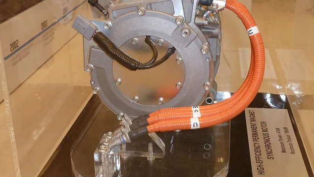
The Rare Earth Crisis vs Materials Substitution: Permanent Magnets for EV Motors
NdFeB is the strongest permanent magnet, but over 70% of rare earth supply comes from China. Alternative materials MnBi, MnAl, and ferrite each offer different tradeoffs.
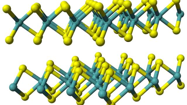
Five Bottlenecks Blocking 2D Semiconductors from the Fab
MoS₂, WS₂ and other 2D semiconductors promise to extend Moore's Law, but at least five industrialization bottlenecks stand between a lab-scale flake and a wafer-scale product.
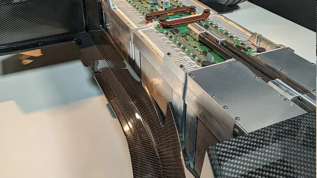
The Materials Science of Lithium-Ion Battery Recycling: Mining the Urban Mine
Battery recycling is not optional — 500,000 tons of Li-ion batteries will retire by 2025. But pyrometallurgy, hydrometallurgy, and direct regeneration each face different materials challenges.